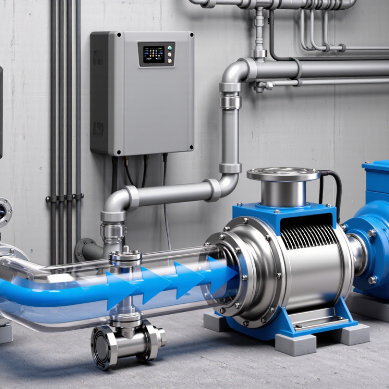
What Is a Pump Inverter and How Does It Work?

A Pump Inverter is a power-control device that adjusts a pump motor’s speed according to changing water demand. Unlike a traditional pump that runs at one fixed speed, it can respond gradually. A pressure sensor measures the system, while the inverter changes the motor’s frequency and voltage. The pump then delivers only the flow required.

This process is easy to notice in daily operation. When a tap opens, pressure begins to fall. The controller increases motor speed smoothly, reducing the sudden surge common with basic on-off systems. When demand decreases, the motor slows down instead of continuing at full power. This can lower energy use, reduce pipe stress, and improve pressure stability. It may also reduce noise in residential booster systems.

The result is practical, but not automatic perfection. Correct sizing still matters. A poorly matched pump, sensor, or pressure setting can cause cycling, overheating, or weak flow. Installation should follow the manufacturer’s instructions and applicable electrical requirements. Technicians typically check motor compatibility, grounding, ventilation, and protection settings before commissioning the system. Small details matter.

This guide explains the main components, control process, benefits, and limitations of a Pump Inverter. It also considers real operating conditions, including fluctuating demand, dry-running risks, and maintenance needs. Some systems perform exceptionally well. Others reveal problems only after weeks of use. Careful testing remains essential.

What Is a Pump Inverter and How Does It Work?

Pump Inverter Definition: Variable-Frequency Drives at 50 or 60 Hz

What Is a Pump Inverter and How Does It Work?

A pump inverter is a variable-frequency drive designed to control motor speed. Its key setting is frequency, commonly 50 or 60 Hz. The inverter first converts incoming AC power into DC. It then recreates AC power at a selected frequency and voltage. Lower frequency usually means lower pump speed. For centrifugal pumps, the affinity laws link speed with performance: flow changes with speed, head changes with speed squared, and power changes with speed cubed.

This matters because motor-driven systems consume about 46% of global electricity, according to the International Energy Agency. The U.S. Department of Energy’s Pumping Systems Sourcebook also explains that correctly matched pump controls can reduce throttling losses and improve system efficiency. At 50 Hz, a pump may operate near its rated regional supply frequency. At 60 Hz, the same motor can run faster, but heat, vibration, and pressure may rise. The result is not always better. Static head, pipe friction, and changing demand can weaken the simple calculation.

Tips: Check the motor nameplate before programming 50 or 60 Hz. Measure flow, pressure, and current during real operation. Keep minimum speed limits within the motor and pump manufacturer’s guidance. A pressure sensor can support automatic control, but poor sensor placement creates unstable cycling. I have found that “lower speed equals lower cost” is useful, yet incomplete. Pump curves and site measurements still decide whether the saving is real.

Pump Inverter Performance at 50 Hz and 60 Hz

A pump inverter, also called a variable-frequency drive, changes the motor frequency to regulate pump speed. Using the pump affinity laws, speed and flow vary approximately in proportion to frequency, while head varies with the square of speed and shaft power with the cube. The values shown are idealized percentages relative to the same pump operating at its 60 Hz nominal frequency.

Core Components: Rectifiers, DC Links, IGBTs, and Control Processors

A pump inverter adjusts motor speed by changing the frequency and voltage supplied to the pump motor. This allows water flow and pressure to match actual demand. Instead of running at full speed continuously, the motor may slow during low consumption. That can reduce energy use and mechanical stress.

The rectifier is the input stage. It converts incoming alternating current into pulsating direct current. A DC link then smooths this power with capacitors and sometimes an inductor. The stored energy forms a steadier electrical bridge between the input and output stages. IGBTs switch this DC voltage thousands of times per second. Their pulse pattern creates a controlled three-phase waveform for the motor. Switching timing matters. Poor timing can create heat, noise, or unwanted vibration.

A control processor acts as the decision center. It reads pressure, flow, current, temperature, and motor feedback through connected sensors. Then it adjusts the IGBTs within milliseconds. For example, a pressure sensor may detect a falling line pressure after a valve opens. The processor raises motor speed gradually, rather than producing a harsh surge. In field work, sensor placement often matters as much as software settings. A sensor installed near turbulence can report unstable readings. That detail is easy to overlook. Protective functions also monitor dry running, overload, phase loss, and excessive temperature. The system is precise, but not perfect. Incorrect parameters can still cause cycling, even when every core component operates normally.

Operating Sequence: AC Conversion, PWM Switching, and Motor-Speed Control

What Is a Pump Inverter and How Does It Work?

A pump inverter regulates motor speed instead of running the motor at one fixed speed. Its operating sequence begins when incoming AC power reaches the drive. A rectifier converts this AC supply into DC voltage. Capacitors then smooth the DC link, reducing sharp voltage fluctuations. The controller measures current, temperature, and input conditions before allowing the motor to start. This protective pause matters in dusty pump rooms and unstable electrical systems.

The inverter then uses power switches to rebuild the DC voltage into controlled AC output. These switches turn on and off thousands of times per second. This process is called pulse-width modulation, or PWM. The switching pattern creates an adjustable voltage and frequency for the motor. Lower frequency usually means lower motor speed. The controller also adjusts voltage to maintain a suitable volts-per-hertz relationship. Smooth ramping prevents sudden torque and reduces water hammer in long pipelines.

A pressure sensor may report that demand has fallen. The inverter responds by reducing frequency, often within seconds. When several outlets open, it raises frequency to recover pressure. Practical commissioning is less perfect than a diagram suggests. Sensor delay can cause hunting, while poor tuning may create audible motor noise. Cable length, heat, grounding, and minimum motor speed also affect reliability. I have found that conservative acceleration settings often protect the system better than aggressive response. Yet every pump curve differs, so copied settings deserve careful review.

Hydraulic Laws: Flow ∝ Speed, Head ∝ Speed², and Power ∝ Speed³

What Is a Pump Inverter and How Does It Work?

A pump inverter changes motor speed by adjusting electrical frequency. This lets the pump match changing water demand instead of running constantly at full speed. The key hydraulic relationships are simple: flow is proportional to speed, head is proportional to speed squared, and power is proportional to speed cubed. If speed falls to 80%, flow becomes about 80%. Head drops to roughly 64%, while power may fall to only 51%. That power reduction can be significant.

The equations are useful, but field conditions deserve respect. A pump moving water through long pipes may face changing friction, valves, and elevation. The system curve can limit the expected savings. Real systems disagree. I have seen a calculated speed setting produce weak pressure because the pump was operating below its useful range. A pressure sensor, flow meter, and motor protection settings help verify performance. The inverter should also avoid rapid speed changes, which can create pressure surges and mechanical stress. Efficiency is not constant, either. Motor losses, pump efficiency, and cooling requirements affect the result. A lower speed is not automatically better. The design must preserve minimum flow and prevent overheating. That detail is easy to miss. Regular readings can reveal whether the hydraulic model matches reality, or whether the original assumptions need rethinking.

Selection Criteria: Voltage, Motor kW, IP Rating, Sensors, and Protection

What Is a Pump Inverter and How Does It Work?

Selection Criteria: Voltage, Motor kW, IP Rating, Sensors, and Protection

A pump inverter changes motor speed by adjusting frequency and voltage. This helps match pumping output to real demand. It can reduce water hammer and lower starting current. The voltage must match the supply and motor nameplate. Check single-phase or three-phase operation carefully. A small mismatch can cause unstable operation or motor damage. Motor kW matters, but rated current matters more. Select the inverter from the motor’s actual amperage, not guesswork.

Keep the margin reasonable. Oversizing may reduce control accuracy. Undersizing can trigger overload faults during peak demand. The IP rating should suit the installation area. IP20 may fit a clean control cabinet. IP55 or higher is more suitable near splashing water and dust. Even a strong enclosure needs correct cable glands. Sensors provide the feedback that makes automatic control useful. Pressure transducers, flow sensors, and level switches are common choices. Confirm their signal range, such as 4–20 mA or 0–10 V.

Protection functions deserve close attention. Look for dry-run detection, overload, phase loss, overvoltage, undervoltage, overheating, and locked-rotor protection. A pressure sensor mounted in the wrong pipe location can produce misleading readings. That detail is easy to miss. During commissioning, compare displayed pressure with a calibrated gauge. Record motor current at low, normal, and maximum demand. Real systems are rarely perfect. Temperature, pipe friction, and changing water levels may require later adjustment.

What Is a Pump Inverter and How Does It Work? - Selection Criteria: Voltage, Motor kW, IP Rating, Sensors, and Protection

Selection Criterion What It Means Typical Data or Options Selection Guidance Practical Check
Operating Principle A pump inverter, commonly called a variable frequency drive (VFD), regulates the motor’s speed by varying the frequency and voltage supplied to the motor. Adjustable output frequency, commonly 0–50 Hz or 0–60 Hz; some applications use extended frequency ranges specified by the motor and pump manufacturer. Use speed control to match pump output with demand, maintain pressure, reduce throttling losses, and support smoother starting. Confirm that the motor is suitable for inverter operation and that the pump can operate safely across the intended speed range.
Input Voltage The incoming electrical supply available at the installation site. Single-phase 200–240 V; three-phase 200–240 V; or three-phase 380–480 V are common drive supply classes. Select a drive whose rated input voltage and phase configuration match the supply. Do not assume a three-phase motor can be connected directly to a single-phase output. Check the measured site voltage, frequency, number of phases, permissible voltage tolerance, and available short-circuit current.
Motor Voltage and Phase The electrical requirements of the connected pump motor. Typical low-voltage motor ratings include 230/400 V or 400/690 V, with three-phase operation commonly used for larger pumps. Match the drive output voltage and motor connection method, such as delta or star, to the motor nameplate and local supply arrangement. Read the motor nameplate before wiring. Verify rated voltage, rated current, frequency, speed, and connection diagram.
Motor Rating in kW The mechanical power rating of the motor, used as an initial guide for drive sizing. Common pump motor sizes include 0.75, 1.5, 2.2, 4, 7.5, 11, 15, 22, and 30 kW. Choose a drive with a continuous output current equal to or greater than the motor’s rated current. kW alone is not sufficient for final selection. Compare the motor full-load current with the drive’s rated output current, especially for high-efficiency, high-inertia, or heavily loaded pumps.
Duty and Overload Capacity The drive’s ability to handle starting and temporary load increases. Many general-purpose drives provide approximately 110–120% overload for 60 seconds, but the exact value depends on the operating duty and model. For centrifugal pumps, normal-duty sizing is often suitable; positive-displacement pumps may require higher torque and heavier-duty sizing. Check starting torque, acceleration time, pump type, fluid viscosity, and the drive’s overload curve.
Enclosure / IP Rating The level of protection against solid objects, dust, and water ingress. IP20 is commonly used inside electrical cabinets; IP54, IP55, and IP66 provide progressively greater protection for exposed installations. Use IP20 in a clean, dry, ventilated cabinet. Consider IP55 or higher for dusty, damp, or washdown environments, subject to temperature and installation limits. Assess dust, humidity, water jets, condensation, corrosive chemicals, outdoor exposure, and the enclosure’s cooling method.
Pressure Sensor Provides feedback so the inverter can increase or decrease pump speed to maintain a target pressure. Common signals include 4–20 mA and 0–10 V. Typical pressure transducer ranges may include 0–6 bar, 0–10 bar, or 0–16 bar. Select a sensor range that covers the normal operating pressure while leaving reasonable measurement margin above the setpoint. Confirm signal type, pressure range, process connection, wetted-material compatibility, accuracy, and cable shielding requirements.
Flow, Level, and Temperature Sensors Additional feedback devices help control demand and protect the pump system. Options include flow switches, 4–20 mA flow meters, float switches, level transmitters, thermistors, and motor temperature sensors. Use the sensor that corresponds to the control objective: constant pressure, minimum flow, tank level, dry-run prevention, or temperature monitoring. Verify input compatibility, fail-safe behavior, sensor location, response time, and whether the sensor requires an external power supply.
Pump Protection Functions Built-in functions reduce the risk of damage caused by abnormal operating conditions. Common functions include dry-run detection, low-flow sleep, underload detection, pipe-break detection, maximum pressure control, and anti-jam routines. Select functions based on the pump type, water source, pipework, pressure requirements, and consequences of loss of flow. Confirm whether protection is automatic, adjustable, alarm-only, or configured to stop and restart the pump.
Electrical Protection Protects the inverter and motor from electrical faults and thermal stress. Typical functions include overcurrent, short circuit, overload, overvoltage, undervoltage, input phase loss, output phase loss, ground fault, and inverter overtemperature protection. Use the drive’s internal protection together with correctly rated upstream disconnects, fuses or circuit breakers, grounding, and motor protection practices. Check fault codes, trip thresholds, reset behavior, short-circuit rating, grounding arrangement, and local electrical requirements.
Control Mode Determines how the inverter calculates and controls motor output. Common modes include scalar V/f control, sensorless vector control, and closed-loop control using a speed or pressure feedback signal. V/f control is often adequate for standard centrifugal pumps; vector or closed-loop control may improve low-speed torque and regulation. Match the control mode to the required pressure stability, speed range, torque demand, and feedback hardware.
Motor Cable and EMC The inverter produces fast voltage pulses that can affect cable insulation, bearings, and electromagnetic compatibility. Installation may require shielded motor cable, proper cable separation, grounding, output filters, or a common-mode choke, depending on cable length and system design. Follow the inverter and motor instructions for maximum cable length, switching frequency, shielding, and filter selection. Check cable cross-section, insulation rating, cable route, grounding continuity, and potential interference with sensors or communication wiring.
Environmental Conditions Temperature, altitude, humidity, and contamination affect the drive’s permissible output and service life. Many drives require derating at elevated ambient temperatures or high installation altitudes; exact limits vary by design. Allow adequate ventilation and apply the manufacturer’s derating requirements when ambient conditions exceed the standard reference conditions. Record ambient temperature, altitude, humidity, corrosive exposure, enclosure heat dissipation, and cooling-fan requirements.
Communication and Automation Allows the inverter to exchange commands, status, alarms, and operating values with a control system. Typical interfaces include digital inputs, relay outputs, analog inputs and outputs, RS-485, and industrial communication networks. Choose the interface required for remote start/stop, pressure setpoint adjustment, alarm reporting, energy monitoring, or multi-pump coordination. Confirm protocol compatibility, cable requirements, network topology, parameter access, and the required loss-of-communication response.
Important sizing note: The final inverter selection should be based on the motor nameplate current, supply voltage and phase, pump duty, overload requirement, installation environment, sensor configuration, and applicable electrical standards—not on motor kW alone.
Get a Quote
910-483-7828